Cycloidal Drive
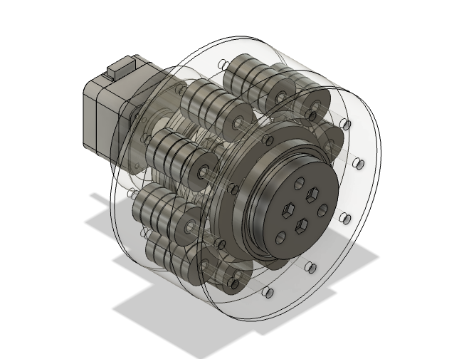
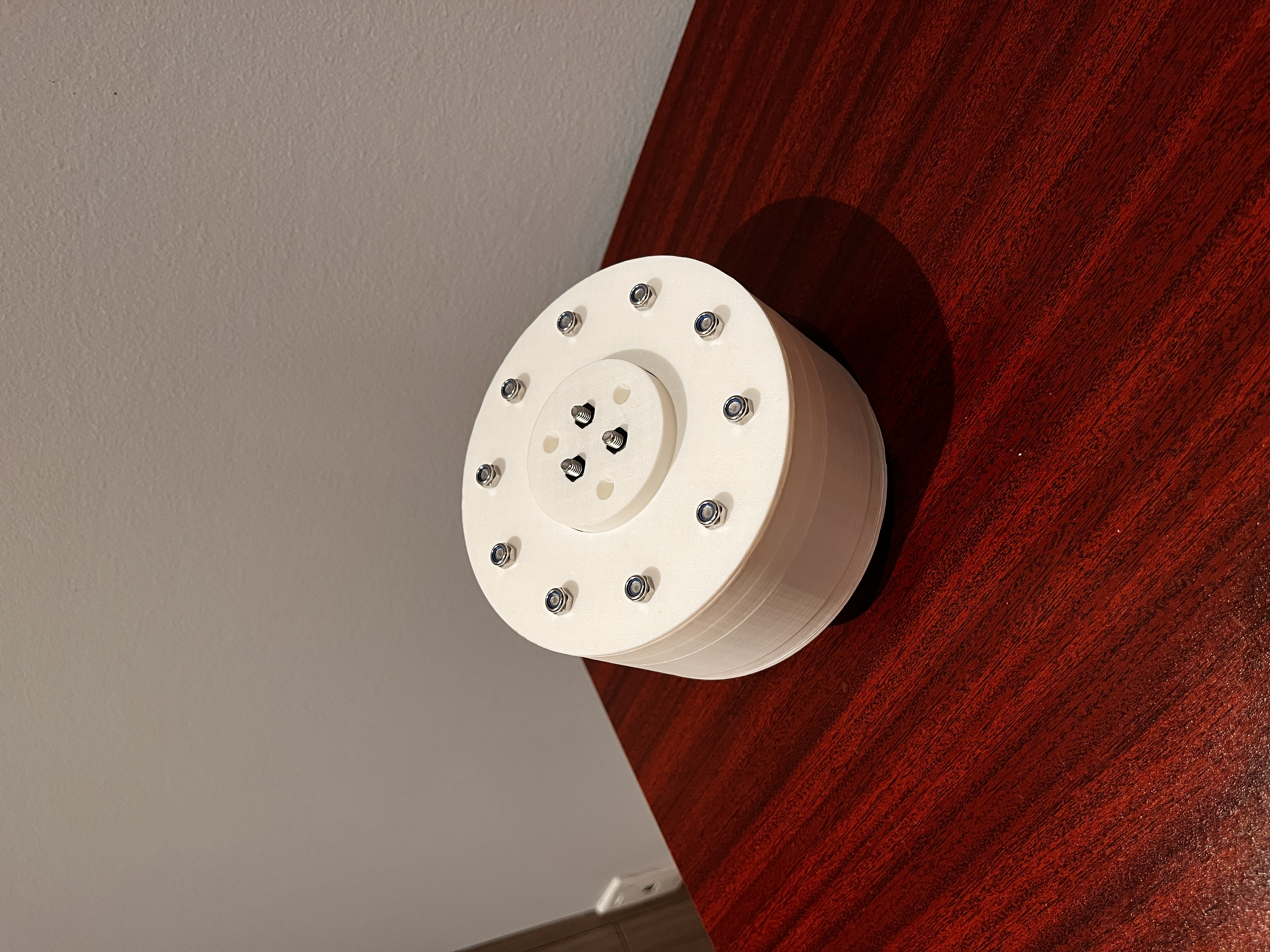
Cycloidal gearboxes are a special type of gearboxes that can create large gear reductions with minimal backlash with the use of roller pins and cycloidal disks. This homemade gearbox is made from 3D printed pieces, bearings bought from amazon, and standard M5 screws.
When designing the disk it is important to get the right geometry for the cycloidal disk with consideration to a couple of parameters. Here are the steps I used to determine those parameters.
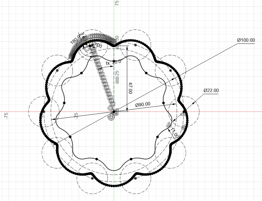
First, the pin diameter which was 22mm and the radius would be 11mm. This parameter was based on the OD of the bearing which I used as roller pins inside the cycloidal drive. Then after putting some circles down in fusion, visually it made sense to have 10 teeth to get a 1:9 gear ratio. To find the gear ratio for cycloidal drives use the following equation:
number of pins/(number of pins - number of lobes on the disk)
Usually the difference between the pins and the lobes is 1 so if I had 10 teeths, the reduction ratio would be 9.
Next I determined the radius of which the pins will be placed in this scenario I had a diameter of 100mm just based on looking at the 2D sketch on CAD.
Then, I can determine the eccentricity value which is usually half to quarter of the pin radius in this scenario it is 3mm.
Next we will need the two circles to create the points for the spline that creates the cycloidal shape based on the following equations:
gear ratio = r1 / r2 = 9
r = d / 2 = 100 / 2 = 50
r1 = gear ratio * r2
r1 = r-r2
Solving these equations, r1 = 45, r2 = 5. Using this information I drew two circles from tangent to each other with the larger circle placed in the center.
Now I can create a line that is the length of the eccentricity from the center of the smaller circle that I just created. Then I created an angle measurement between this line and the line that connects the center of the r1 circle to the r2 circle. The angle from this line to the vertical should be the angle between eccentric line with the r1 line divided by the gear ratio which is 9.
Then changing the angle of the eccentric line, I can create dots along the end of the eccentric line. Using splines I can then connect the dots and create a offsets that moves the shape in the radius of my pins to create the disk shape.
For next bit of geometry, the holes that are placed within the cycloidal disks should have a diameter of the diameter of the output pins plus two times the eccentricity value. The distance that the output pin is placed from the center should be the same distance that the holes on the cycloidal disk is placed from the center.
Lastly, for the input shaft, the distance between center of the input shaft and the center of the eccentric bearing should be half the eccentricity value.
This might seem compliated but these two videos and the solid works tutorial combined will cover all of the important information.
Design a cycloidal gear step by step How to Design a Cycloidal Disk in Fusion 360 Building a Cycloidal Drive with SolidWorks A Great Onshape Feature ScriptThis cycloidal shape drawing process can also be done with parametric equations as well, although it is not ready in fusion360 yet with the following equations.
X = (R*cos(t))-(Rr*cos(t+arctan(sin((1-N)t)/((R/EN)-cos((1-N)t)))))-(Ecos(Nt))
Y = (-R*sin(t))+(Rrsin(t+arctan(sin((1-N)t)/((R/EN)-cos((1-N)t)))))+(Esin(Nt))
If the cycloidal drive is designed perfectly, there should only be one point of contact with every pin from each lobe on the cycloidal disk.
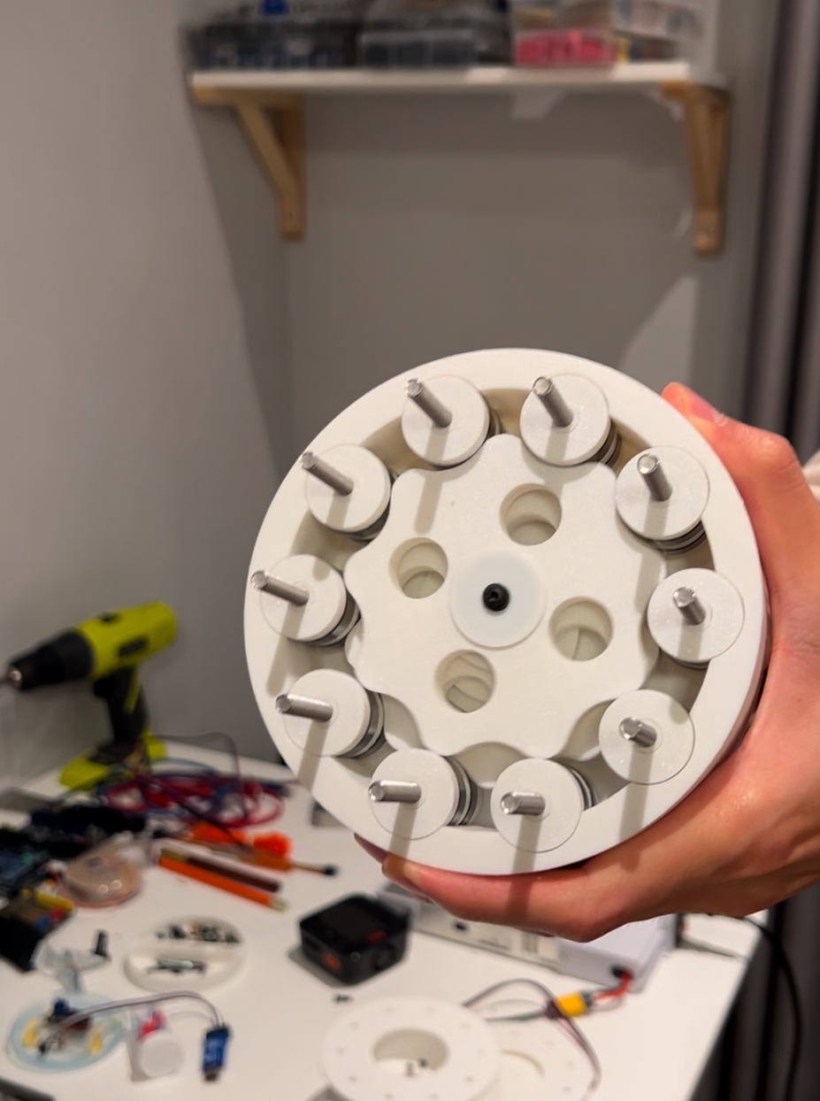
Overall no documentation allowed me to make this on the first try. I went through a couple of prototypes with regards to disk shapes, the input pin size, the output pin sizes, and the geometry to get things rotating properly.
This documentation isn’t written for a tutorial, but feel free to reach out of you have any questions. The next step would be to connect a NEMA motor with the cycloidal drive to do some testing.